7.4 - Access Fittings and Process Stubs
Module: Type I Small Appliances
Regulatory verification date: August 11, 2026
Primary authority: Current 40 CFR §§ 82.152, 82.154, 82.156, and 82.158 together with current EPA Section 608 Type I test-topic guidance
Course role: Explains how technicians obtain temporary access to the sealed refrigerant circuit of a small appliance, how process stubs and solderless or piercing access fittings are used, how tubing material affects the access method, and how access work must minimize refrigerant emissions and leave the appliance properly sealed after service
Learning Objectives
After completing this section, a student should be able to:
- Define a process stub using the current Section 608 definition.
- Explain why small appliances are required to have a process stub unless they contain only refrigerants exempted from the applicable venting prohibition.
- Distinguish a process stub from a permanent service valve or servicing aperture.
- Explain the purpose and basic operation of a piercing access valve.
- Explain the broader category of solderless access fittings and how a piercing valve fits within that category.
- Explain why many solderless access fittings are considered temporary service devices.
- State the current EPA Type I exam-topic expectation that solderless access fittings should be removed at the conclusion of service.
- Explain why leak checking is important after installing an access fitting and after resealing or repairing the tubing.
- Describe how copper and aluminum tubing affect the selection and use of access fittings and repair methods.
- Explain why fitting size, tubing condition, and manufacturer compatibility must be checked before piercing or clamping onto a refrigerant line.
- Explain how low-loss hoses and careful connection/disconnection practices reduce emissions during Type I service.
- Apply access-fitting concepts to common small-appliance examination scenarios.
Introduction
A small appliance is normally:
factory manufactured
+
factory charged
+
hermetically sealed
That construction is one reason small appliances often do not have the same permanent service-valve arrangement found on larger field-installed refrigeration systems.
Yet a technician still needs a controlled way to:
- Recover refrigerant.
- Measure pressure when appropriate.
- Evacuate the system.
- Recharge the system.
- Perform certain repairs.
- Prepare the appliance for disposal.
The access point commonly associated with a small appliance is the:
process stub
Current 40 CFR §82.152 defines a process stub as a length of tubing that provides access to the refrigerant inside a small appliance or room air conditioner and that can be resealed at the conclusion of repair or service.
The basic service concept is:
sealed refrigerant circuit
→ process stub or suitable tubing access point
→ temporary service access
→ recovery / service
→ remove temporary fitting when appropriate
→ reseal tubing
→ leak check
The important Type I principle is not simply:
pierce the tube
It is:
Create the access needed to perform compliant service while minimizing refrigerant release and restoring the refrigerant circuit to a properly sealed condition.
Key Concepts
1. A Process Stub Is Part of the Small-Appliance Access Strategy
A process stub is a short length of tubing connected to the refrigerant circuit.
It allows a technician to gain access to the refrigerant without treating the entire appliance as if it had permanent service valves.
The process stub may support activities such as:
- Refrigerant recovery.
- Pressure measurement.
- Evacuation.
- Charging.
- Repair.
- Disposal preparation.
Conceptually:
Refrigerant circuit
        ↓
   process stub
        ↓
temporary access fitting
        ↓
service / recovery
        ↓
remove fitting when appropriate
        ↓
reseal stub
2. Current Federal Rules Require a Process Stub on Covered Small Appliances
Current 40 CFR §82.154(e)(2) prohibits the sale or distribution of a covered small appliance unless it is equipped with a process stub to facilitate refrigerant removal during servicing and disposal, except for appliances containing only refrigerants that are exempt from the applicable venting prohibition.
This is an important distinction.
For covered equipment:
small appliance
→ process stub
while appliances other than small appliances generally use the separate regulatory concept:
servicing aperture
The detailed distinction was introduced in Section 5.3.
3. A Process Stub Is Not Necessarily a Service Valve
A process stub is:
tubing access
not automatically:
permanent Schrader-type service valve
The stub may initially be:
- Pinched closed.
- Brazed closed.
- Capped or sealed by another factory method.
- Left as a short sealed tube intended for service access.
A technician may attach a temporary access device to the stub when the service procedure requires it.
4. A Piercing Access Valve Creates Access Without First Cutting the Tube Open
A piercing access valve is a clamp-on or saddle-type service device designed to:
- Clamp onto compatible tubing.
- Seal around the tubing surface.
- Drive a piercing needle or point through the tubing wall.
- Create a controlled refrigerant-access passage.
- Provide a service connection for a hose or gauge.
The conceptual sequence is:
select compatible tube
→ install valve body
→ tighten/seal fitting correctly
→ pierce tube
→ establish service connection
A piercing valve is useful because it can create access without initially cutting the line open and releasing the refrigerant charge.
5. Piercing Valve and Solderless Access Fitting Are Related Terms
A solderless access fitting is a broader term for a fitting that can provide refrigerant-circuit access without brazing or soldering the fitting onto the tubing.
A piercing access valve is one common type.
Therefore:
piercing access valve
→ usually a type of solderless access fitting
but:
solderless access fitting
→ does not always mean exactly one valve design
Different products may use:
- Clamp-on bodies.
- Saddle configurations.
- Mechanical seals.
- Piercing needles.
- Replaceable service cores.
- Other manufacturer-specific mechanisms.
Always use the fitting according to its own instructions and material limitations.
Process Stubs
1. Current Regulatory Definition
Current 40 CFR §82.152 defines process stub as a length of tubing that:
- Provides access to refrigerant inside a small appliance or room air conditioner.
- Can be resealed at the conclusion of repair or service.
For exam preparation, memorize the two essential ideas:
ACCESS
+
RESEALABLE
2. Why the Process Stub Is Useful
Many small appliances are factory sealed and may not have conventional permanent service valves.
The process stub provides a controlled location where a technician can gain access without selecting a random point in the refrigerant circuit.
A suitable process stub can reduce the chance of damaging:
- Capillary tubing.
- Heat-exchanger tubing.
- Compressor shell connections.
- Factory joints.
- Other delicate refrigerant-circuit components.
3. Typical Process-Stub Locations
The exact location varies by manufacturer and appliance.
A process stub may be connected near:
- Compressor suction tubing.
- Compressor discharge tubing.
- Factory charging connection.
- Another accessible portion of the refrigerant circuit.
Do not assume that every short sealed tube is automatically the correct service access point.
Confirm the:
- Refrigerant-circuit layout.
- Manufacturer documentation.
- Tube material.
- Tube diameter.
- Intended service location.
4. Factory Pinch-Offs
Some small appliances are charged at the factory through a process tube and then sealed by a pinch-off and brazing or another closure method.
Such a tube can later provide service access if the appliance design and repair procedure permit.
The important concept is:
factory charge point
→ sealed after manufacturing
→ may serve as process stub for later service
Do not cut or reopen the tube until the applicable recovery and service procedure has been established.
5. Process Stub Versus Servicing Aperture
| Feature | Process Stub | Servicing Aperture |
|---|---|---|
| Common regulatory association | Small appliances / room air conditioners | Appliances other than small appliances |
| Physical form | Length of tubing | Access opening or service connection |
| Primary purpose | Refrigerant access and later resealing | Facilitate refrigerant removal |
| Typical Type I importance | High | Secondary comparison concept |
For Type I:
SMALL APPLIANCE
→ think PROCESS STUB
Piercing Access Valves
1. Basic Construction
A typical piercing access valve has:
- A clamp or saddle body.
- A gasket or sealing surface.
- Fasteners.
- A piercing needle or stem.
- A service connection.
When correctly installed, the valve seals against the tubing before or as the tubing wall is pierced.
2. Why the Seal Must Be Established Before Access Is Opened
The desired sequence is:
secure fitting
→ establish seal
→ pierce tubing
→ connect / recover / service
not:
puncture tubing
→ then try to control escaping refrigerant
The fitting and service connection should be prepared so that refrigerant loss is minimized.
3. Correct Tubing Size Matters
Piercing valves are designed for specific tubing diameters or diameter ranges.
A valve that does not match the tube can:
- Fail to seal.
- Distort the tubing.
- Slip.
- Crack or crush the tubing.
- Create a persistent leak.
Therefore:
Never assume that one piercing valve fits every small-appliance tube.
Check the fitting manufacturer’s approved:
- Tube diameter.
- Tube material.
- Wall condition.
- Installation orientation.
- Tightening procedure.
4. Select a Straight, Sound Section of Tubing
A temporary clamp-on fitting should normally be placed only on a tubing section that can support the fitting correctly.
Avoid selecting a location that is:
- Sharply bent.
- Flattened.
- Corroded.
- Cracked.
- Heavily oxidized.
- Directly on a brazed joint.
- So close to another component that the fitting cannot seat evenly.
- On a capillary tube or other tubing too small or delicate for the fitting.
Manufacturer instructions control the actual acceptable installation location.
5. Tighten Correctly
Insufficient tightening can cause leakage.
Excessive tightening can:
- Deform soft tubing.
- Damage the fitting.
- Cut the gasket.
- Crush thin-wall tubing.
Use the manufacturer’s specified installation method rather than tightening “as hard as possible.”
6. Piercing Is Not the Same as Cutting Open the Circuit
A properly installed piercing access fitting creates a controlled access passage while the tubing remains enclosed by the fitting.
This is one reason piercing access valves are useful during recovery from sealed small appliances.
However, once the fitting is installed and the refrigerant circuit is accessed, the technician must still follow all applicable:
- Recovery requirements.
- Manufacturer procedures.
- Safety requirements.
- Emission-minimization practices.
Solderless Access Fittings
1. Why “Solderless” Matters
A solderless fitting can be installed without using a torch to attach the fitting.
This can be useful when:
- Refrigerant is still present and must first be recovered.
- The technician needs temporary access before a permanent repair.
- The appliance contains a refrigerant for which ignition-control procedures are especially important.
- The tube material or appliance design makes a mechanical temporary fitting appropriate.
It does not mean that every solderless fitting is suitable for every refrigerant or tubing material.
2. EPA Type I Test Topic: Remove Solderless Access Fittings After Service
EPA’s current Type I test-topic guidance states that technicians should remove solderless access fittings at the conclusion of service.
This is a high-priority examination concept.
The intended sequence is:
install temporary access fitting
→ recover / service appliance
→ remove temporary fitting
→ permanently reseal or repair tubing
→ leak check
Do not memorize:
piercing valve stays permanently installed
as a general Type I rule.
3. Why Removal Is Good Service Practice
A clamp-on piercing fitting can create additional possible leak paths at:
- The gasket.
- The clamp joint.
- The piercing stem.
- The service core or cap.
- The tubing penetration.
Leaving a temporary fitting indefinitely may increase the chance of future leakage.
For that reason, when the service procedure calls for removal, the refrigerant circuit should be restored using a suitable permanent closure or repair method.
4. Temporary Does Not Mean Careless
A temporary fitting still must:
- Be compatible with the refrigerant.
- Be compatible with the tubing.
- Seal correctly.
- Be installed securely.
- Be leak checked.
- Be connected using appropriate hoses.
- Be removed without avoidable refrigerant release.
Leak Checking Access Fittings
1. Leak Check After Installing the Access Fitting
Once the fitting is installed and the refrigerant circuit is accessible, check the fitting area for leakage.
Potential leak points include:
- Fitting-to-tube seal.
- Gasket.
- Valve stem.
- Service core.
- Cap.
- Hose connection.
The exact leak-checking method depends on:
- Refrigerant.
- System condition.
- Pressure available.
- Appliance design.
- Applicable safety requirements.
Leak-detection methods are developed in:
Section 6.6 - Leak Detection Methods.
2. Leak Check During Service
Watch for signs that the temporary access fitting is not maintaining a seal.
Possible indications include:
- Refrigerant detector response.
- Bubble formation with an approved bubble solution.
- Hissing.
- Oil residue.
- Unexpected pressure loss.
- Frosting at an unintended leak point.
Do not use a flame as a leak detector.
3. Leak Check After Permanent Resealing
After the temporary access fitting is removed and the process stub or tubing is permanently resealed:
repair / reseal
→ leak check
→ confirm integrity
The completed service should not leave a new leak created by the access operation.
4. Leak Checking Does Not Replace Recovery Requirements
Finding a leak does not permit intentional venting of the remaining refrigerant.
If the appliance must be opened:
recover refrigerant as required
→ perform repair
→ leak check repaired area
The recovery requirement from Section 7.3 still applies.
Copper Tubing
1. Copper Is Common in Small-Appliance Refrigerant Circuits
Copper tubing is widely used for:
- Suction lines.
- Discharge lines.
- Process tubes.
- Capillary systems.
- Condenser or evaporator connections.
However, a small appliance may contain several different tubing materials in one refrigerant circuit.
Do not assume:
all tubing is copper
2. Copper Is Relatively Serviceable
Copper can often be:
- Cut.
- Pinched.
- Flared in suitable applications.
- Brazed using appropriate procedures.
- Connected to compatible mechanical fittings.
This makes copper process stubs convenient service-access points.
3. Avoid Damaging Thin Tubing
Small-appliance tubing can be relatively small and thin.
Overtightening a clamp-on valve can:
- Flatten the tube.
- Create stress concentration.
- Produce cracks.
- Prevent correct sealing after the fitting is removed.
A correct mechanical seal is preferable to excessive force.
4. Do Not Apply Heat Until Refrigerant Has Been Properly Recovered
If a permanent repair requires brazing or other hot work:
recover refrigerant
→ establish safe work condition
→ perform hot work
Do not heat refrigerant-containing tubing as a substitute for proper recovery.
This is especially important when the appliance contains a flammable refrigerant.
Aluminum Tubing
1. Some Small Appliances Use Aluminum Refrigerant Tubing
Aluminum can be found in:
- Heat exchangers.
- Connecting tubing.
- Compact refrigeration circuits.
- Newer appliance designs.
The technician must identify the tubing material before selecting a fitting or repair technique.
2. Copper-Specific Methods May Not Be Suitable for Aluminum
Do not assume that:
method works on copper
→ method automatically works on aluminum
Aluminum differs from copper in:
- Mechanical properties.
- Surface oxide behavior.
- Joining methods.
- Heat sensitivity.
- Compatible repair materials.
A fitting or repair method must be approved for the actual tube material.
3. Aluminum Can Be Easily Damaged by the Wrong Clamp or Piercing Method
A mechanically attached valve can damage aluminum tubing if:
- The fitting diameter is incorrect.
- The tubing wall is too thin.
- The clamp load is excessive.
- The tubing is already distorted or corroded.
- The fitting manufacturer does not approve use on aluminum.
Therefore:
Material compatibility must be verified before installing a piercing or solderless access fitting.
4. Use Manufacturer-Approved Repair Methods
Permanent repair of aluminum tubing may require:
- A material-specific mechanical repair fitting.
- A manufacturer-approved joining process.
- Replacement of the affected component.
- Specialized aluminum repair procedures.
Do not improvise a copper-style repair on aluminum tubing.
Copper-to-Aluminum Transitions
Some appliance refrigerant circuits contain transitions between different metals.
A copper-to-aluminum connection may be:
- Factory manufactured.
- Specially bonded.
- Brazed with a specialized process.
- Mechanically joined.
Avoid placing a temporary piercing valve directly on a transition joint unless the fitting and appliance manufacturer specifically allow it.
A transition joint can be more sensitive to:
- Mechanical loading.
- Heat.
- Corrosion.
- Distortion.
Choose a sound section of compatible tubing instead.
Minimizing Refrigerant Emissions During Access Work
1. The Venting Prohibition Still Applies
Current 40 CFR §82.154 prohibits knowing venting or release of covered refrigerants during maintenance, service, repair, or disposal, subject to the rule’s exemptions and de minimis provisions.
The regulation recognizes that some de minimis release may occur during a good-faith attempt to recover or recycle refrigerant when all applicable required practices are followed.
That does not mean:
small release
→ automatically acceptable
The technician must use the required recovery and service practices.
2. Prepare Before Piercing
Before creating access:
- Identify the refrigerant.
- Confirm the appliance classification.
- Select the recovery method.
- Prepare the recovery equipment.
- Prepare the hose.
- Select the correct access fitting.
- Verify tubing material.
- Verify tubing diameter.
- Inspect the selected access location.
- Confirm the fitting is compatible with the refrigerant and application.
A good sequence is:
plan first
→ access second
not:
pierce first
→ figure out recovery later
3. Minimize Hose Volume
Long or unnecessarily large hoses can contain more refrigerant after service.
Use:
- Appropriate hose length.
- Appropriate hose diameter.
- Low-loss fittings where applicable.
- Correct valve sequence.
This supports the Section 608 goal of minimizing emissions.
4. Close or Isolate Before Disconnecting
Whenever the fitting and equipment configuration permit:
complete recovery
→ isolate / close connection
→ manage trapped hose refrigerant
→ disconnect
Do not simply disconnect a pressurized hose and intentionally release its contents.
5. Use Low-Loss Connections
Current recovery-equipment certification rules require low-loss fittings on hoses for the applicable general recovery-equipment framework.
A low-loss fitting is designed to minimize release when a hose is disconnected.
The service principle is:
connect
→ service
→ isolate
→ disconnect
→ minimize release
6. Temporary Access Should End With a Sound Refrigerant Circuit
The final condition after service should be:
temporary access removed when appropriate
+
tubing properly resealed
+
repair leak checked
+
service connections closed
The goal is not only to complete today’s recovery.
The goal is to avoid creating tomorrow’s refrigerant leak.
Access Fittings and “Opening an Appliance”
Current 40 CFR §82.152 defines opening an appliance broadly as service, maintenance, or repair that would release refrigerant to the atmosphere if the refrigerant had not previously been recovered.
However, connecting and disconnecting hoses and gauges to:
- Measure pressure.
- Add refrigerant.
- Recover refrigerant.
are not, by themselves, considered “opening an appliance” under that definition.
This does not create permission to vent refrigerant.
It simply distinguishes:
connection activity
from:
opening the refrigerant circuit for repair
If the service will actually open the refrigerant circuit, the applicable recovery requirement must be met first.
For a small appliance, see:
Section 7.3 - Type I Recovery Requirements.
Access Point Selection
1. Use the Intended Process Stub When Available
If the manufacturer provides an identifiable process stub:
intended process stub
→ preferred service-access location
unless the service procedure requires another location.
2. Understand High-Side and Low-Side Access
Later Type I recovery procedures depend on whether access is available on:
- High side.
- Low side.
- Both sides.
For a small appliance with an inoperative compressor, EPA’s current Type I test topics specifically include the need to install both high- and low-side access valves when recovering refrigerant.
This is developed in detail in:
Section 7.6 - Recovery with a Failed Compressor.
3. Do Not Confuse Access Point With Recovery Method
The access fitting answers:
Where can I connect?
The recovery method answers:
What moves the refrigerant?
For example:
piercing valve
→ access device
while:
system-dependent recovery
or
self-contained recovery
→ recovery method
Keep these concepts separate.
Temporary Access Workflow
A good Type I workflow is:
Step 1 — Identify the Appliance and Refrigerant
Confirm:
- It is a qualifying small appliance.
- Refrigerant type is known.
- Appropriate safety precautions are established.
Step 2 — Locate the Process Stub or Suitable Access Location
Check:
- Service documentation.
- Tubing layout.
- High-side / low-side needs.
- Accessibility.
- Tube diameter.
- Tube material.
Step 3 — Select the Correct Access Fitting
Verify:
- Diameter range.
- Copper/aluminum compatibility.
- Refrigerant compatibility.
- Pressure suitability.
- Intended temporary-service use.
- Manufacturer instructions.
Step 4 — Prepare Recovery Equipment Before Opening Access
Have ready:
- Recovery equipment.
- Recovery container.
- Hoses.
- Low-loss connections.
- Gauges where needed.
- Leak-detection method.
Step 5 — Install the Fitting
Install according to the fitting instructions.
Do not overtighten.
Step 6 — Establish the Access Passage
Pierce or open the fitting only after the fitting is secured and the recovery connection can be controlled.
Step 7 — Leak Check
Check:
- Tube-to-fitting seal.
- Valve stem/core.
- Hose connection.
Step 8 — Perform Recovery / Service
Follow:
- Section 7.3 recovery endpoint.
- Recovery-machine instructions.
- Applicable Type I procedure.
Step 9 — Remove Temporary Solderless Access Fitting
At the conclusion of service, follow the current EPA Type I exam-topic expectation:
remove solderless access fitting
when the fitting is a temporary service device.
Step 10 — Permanently Reseal the Tubing
Use a material-appropriate and manufacturer-approved method.
Step 11 — Leak Check the Final Repair
Verify that the refrigerant circuit is tight before service is considered complete.
Common Access Devices
| Device | Basic Purpose | Typical Status After Service | Main Exam Point |
|---|---|---|---|
| Process stub | Provides resealable refrigerant access | Remains as part of appliance but is resealed | Small-appliance access |
| Piercing access valve | Mechanically pierces tubing to create service port | Commonly temporary | Secure/seal before piercing; remove when procedure calls for it |
| Solderless access fitting | Provides access without brazing/soldering | Often temporary | EPA Type I topic: should remove after service |
| Permanent service fitting | Provides repeated service connection | May remain if designed as permanent fitting | Not the same concept as temporary piercing valve |
| Low-loss hose fitting | Minimizes release during hose disconnection | Part of recovery/service equipment | Emission minimization |
Important Terms
Access Fitting
A device used to create or provide a connection to the refrigerant circuit for service, measurement, recovery, evacuation, or charging.
Piercing Access Valve
A mechanical access fitting that clamps onto compatible tubing and pierces the tubing wall to create a controlled service connection.
Process Stub
A length of tubing that provides access to the refrigerant inside a small appliance or room air conditioner and can be resealed at the conclusion of repair or service.
Service Connection
A point where a hose, gauge, recovery device, or other service equipment is connected to the refrigerant circuit.
Solderless Access Fitting
A mechanically attached service fitting that does not require soldering or brazing to create the service connection.
Temporary Access Fitting
An access device intended primarily to provide service access during a repair or recovery operation rather than to remain indefinitely as the appliance’s permanent service connection.
Low-Loss Fitting
A hose-end fitting or connection designed to minimize refrigerant release during connection and disconnection.
Servicing Aperture
The regulatory access concept generally associated with appliances other than small appliances; it facilitates refrigerant removal during servicing and disposal.
Reseal
To restore the refrigerant circuit to a closed condition after temporary service access has been removed.
Figures and Diagrams
Figure 7.4.1
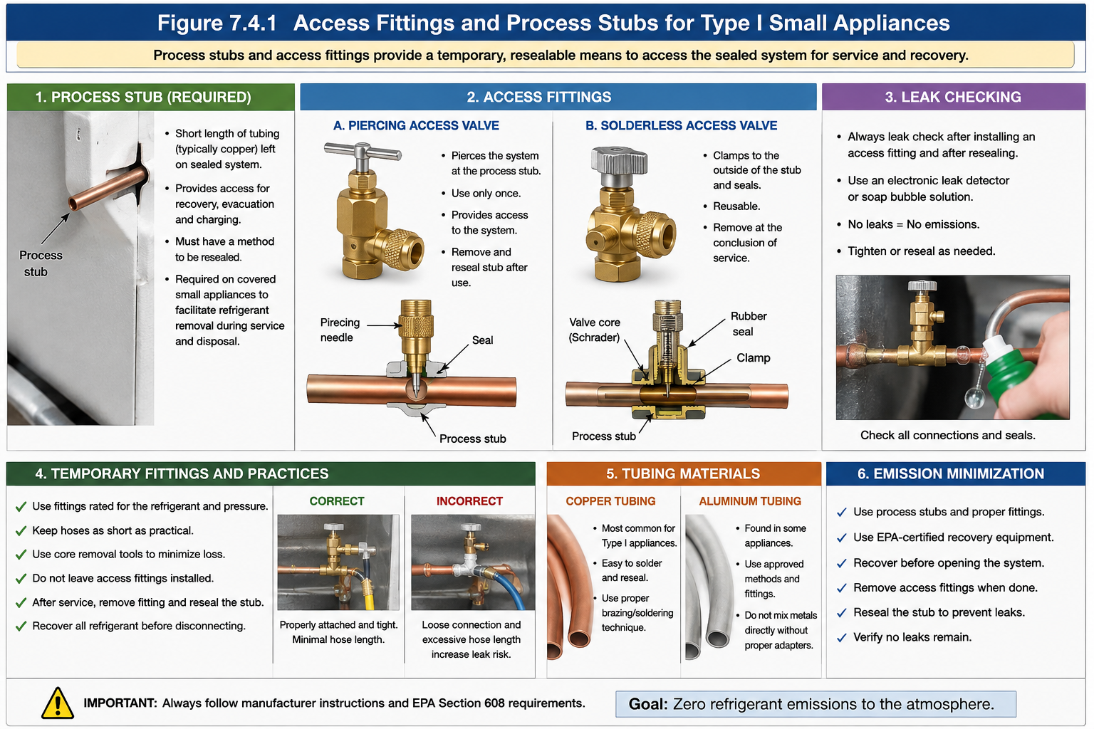
Figure 7.4.1 – A process stub provides resealable access; a temporary piercing fitting can create a controlled service connection and should be removed when the service procedure is complete.
AI-generated instructional figure: It may contain visual inaccuracies. Use the accompanying lesson text and cited authoritative sources to verify technical and regulatory details.
EPA 608 Exam Focus
Highest-Priority Access Concepts
Remember:
Small appliance
→ process stub
Process stub
→ length of tubing
→ provides refrigerant access
→ can be resealed
Piercing valve
→ temporary access fitting
Solderless access fitting
→ should be removed after service
Exam Trap 1 — Process Stub Is a Valve
Incorrect.
A process stub is:
a length of tubing
It may be used with an access valve, but the two are not the same object.
Exam Trap 2 — Leave the Piercing Valve Permanently
EPA’s current Type I test topics specifically include:
Should remove solderless access fittings at conclusion of service
Therefore, the safer exam answer is generally:
temporary fitting
→ remove
→ reseal tubing
Exam Trap 3 — Any Fitting Fits Any Tube
Incorrect.
The technician must consider:
- Tube diameter.
- Tube material.
- Fitting design.
- Tubing condition.
- Manufacturer instructions.
Exam Trap 4 — Copper and Aluminum Are Serviced the Same Way
Incorrect.
Material compatibility matters.
A fitting or permanent repair method suitable for copper may not be suitable for aluminum.
Exam Trap 5 — Access Fitting Eliminates Recovery Requirement
Incorrect.
Creating a service connection does not replace the Type I recovery requirement.
See Section 7.3.
Exam Trap 6 — Piercing the Tube Before Preparing Recovery Equipment
Incorrect service sequence.
The technician should prepare the recovery setup so that opening the access passage does not create avoidable refrigerant release.
Exam Trap 7 — A Temporary Fitting Does Not Need Leak Checking
Incorrect.
A temporary fitting can itself become a leak source.
Check it after installation and check the final permanent repair after removal.
Common Mistakes and Confusing Points
Mistake 1: Calling the Piercing Valve the Process Stub
The process stub is tubing.
The piercing valve is an access device attached to tubing.
Mistake 2: Piercing an Unsuitable Tube Location
Do not choose:
- Capillary tube.
- Sharp bend.
- Crushed section.
- Corroded section.
- Brazed joint.
Use a sound, compatible section according to manufacturer instructions.
Mistake 3: Assuming More Clamp Force Is Better
Overtightening can damage thin tubing and the fitting seal.
Mistake 4: Assuming Aluminum Can Be Repaired Exactly Like Copper
Different materials require different compatible repair methods.
Mistake 5: Leaving a Temporary Fitting Installed Without Considering the Service Procedure
The current Type I exam topic expects solderless access fittings to be removed after service.
Mistake 6: Disconnecting a Pressurized Hose Carelessly
Use low-loss fittings and proper valve sequence to minimize release.
Mistake 7: Failing to Leak Check the Final Repair
A successful recovery procedure is not enough if the access operation leaves the appliance leaking.
Mistake 8: Applying Heat Before Recovery
Hot work should not be performed on a refrigerant-containing circuit as a substitute for proper refrigerant recovery and safe preparation.
Mistake 9: Using the Wrong Diameter Piercing Valve
A poor size match can create leakage or tubing damage.
Mistake 10: Confusing Access Hardware With Recovery Equipment
The piercing valve creates access.
The recovery device removes refrigerant.
These are separate functions.
Concept-Check Questions
Question 7.4-1
What is a process stub?
A. A permanent recovery cylinder connection
B. A length of tubing that provides access to refrigerant in a small appliance or room air conditioner and can be resealed after service
C. The discharge port of a recovery machine
D. A valve used only on low-pressure chillers
Question 7.4-2
Which statement best describes a piercing access valve?
A. It is a clamp-on mechanical fitting that can pierce compatible tubing to create a service connection.
B. It is the same thing as the appliance compressor service valve.
C. It is a required permanent fitting on every small appliance.
D. It is a vacuum pump connection used only after all service is complete.
Question 7.4-3
According to current EPA Type I test topics, what should normally be done with solderless access fittings at the conclusion of service?
A. Paint them to show the appliance has been serviced.
B. Leave them installed permanently in all cases.
C. Remove them and restore the tubing according to the proper service procedure.
D. Open them fully before disconnecting the hose.
Question 7.4-4
Why must the technician verify tubing diameter and material before installing a piercing access valve?
A. Because all refrigerant tubing has the same wall thickness.
B. Because an incompatible fitting can fail to seal or damage the tubing.
C. Because only steel tubing can be pierced.
D. Because process stubs are always made of aluminum.
Question 7.4-5
Which is the best sequence for using a temporary piercing fitting?
A. Pierce the tube first, then locate recovery equipment.
B. Secure and seal the fitting, establish controlled access, perform service, remove the temporary fitting when appropriate, reseal, and leak check.
C. Cut the process stub completely open and allow pressure to fall to atmospheric.
D. Install the fitting on a capillary tube because it has the smallest diameter.
Question 7.4-6
Which statement about copper and aluminum tubing is most accurate?
A. Any repair method suitable for copper is automatically suitable for aluminum.
B. Tube material has no effect on access-fitting selection.
C. Fitting and repair methods must be compatible with the actual tubing material.
D. Aluminum tubing cannot be used in refrigeration appliances.
Question 7.4-7
What is the main purpose of using a low-loss hose connection during service?
A. Increase compressor displacement.
B. Minimize refrigerant release when connections are made or disconnected.
C. Raise condenser pressure.
D. Convert vapor refrigerant into liquid refrigerant.
Question 7.4-8
After a temporary access fitting has been removed and the process stub has been permanently resealed, what should the technician do?
A. Leave without checking because the system was already recovered.
B. Leak check the final resealed or repaired area.
C. Install a second temporary piercing valve immediately.
D. Vent a small amount of refrigerant to confirm flow.
Answers and detailed explanations will be provided in
7.12 - Answers and Explanations.md.
Section Summary
Small appliances are factory-sealed refrigeration systems, so technicians often need a controlled temporary access method.
The most important Type I access concepts are:
- A process stub is a length of tubing that provides refrigerant access and can be resealed after repair or service.
- Current federal rules require covered small appliances to have a process stub to facilitate refrigerant removal during servicing and disposal.
- A piercing access valve is a temporary mechanical device that clamps onto compatible tubing and pierces the tube wall to create service access.
- A piercing access valve is commonly a type of solderless access fitting.
- Current EPA Type I test topics state that solderless access fittings should be removed at the conclusion of service.
- The fitting should be secured and sealed before the tubing is pierced.
- Tube diameter, tube condition, refrigerant compatibility, and tube material must be checked before installing a fitting.
- Copper and aluminum cannot automatically be assumed to use the same access or permanent repair method.
- Temporary access fittings should be leak checked after installation.
- The final permanent reseal or repair should also be leak checked.
- Low-loss hose connections and proper valve sequence help minimize refrigerant emissions.
- Creating an access point does not replace the applicable small-appliance recovery requirement.
The basic service sequence is:
identify correct access location
→ select compatible fitting
→ prepare recovery equipment
→ clamp and seal fitting
→ create access
→ leak check
→ recover / service
→ remove temporary fitting
→ permanently reseal
→ leak check final repair
The next section uses these access concepts to explain recovery when the appliance compressor is operating.
See Section 7.5 - Recovery with an Operating Compressor.
References
Current Regulatory and EPA Sources
-
Electronic Code of Federal Regulations, 40 CFR § 82.152 — Definitions, current definitions of process stub, opening an appliance, small appliance, and related Section 608 terms. Accessed August 11, 2026.
-
Electronic Code of Federal Regulations, 40 CFR § 82.154 — Prohibitions, current venting prohibition, de minimis framework, and appliance-manufacture/sale requirements including process stubs on covered small appliances. Accessed August 11, 2026.
-
Electronic Code of Federal Regulations, 40 CFR § 82.156 — Proper Evacuation of Refrigerant from Appliances, current small-appliance recovery requirements and manufacturer-direction requirement. Accessed August 11, 2026.
-
Electronic Code of Federal Regulations, 40 CFR § 82.158 — Standards for Recovery and/or Recycling Equipment, current recovery-equipment certification requirements, including applicable low-loss fitting requirements. Accessed August 11, 2026.
-
U.S. Environmental Protection Agency, Test Topics — Section 608 Technician Certification, current Type I recovery-technique topics including high- and low-side access for inoperative compressors and removal of solderless access fittings after service. Accessed August 11, 2026.
-
U.S. Environmental Protection Agency, Definitions of Section 608 Terms, current EPA plain-language definitions and small-appliance terminology. Accessed August 11, 2026.